I.The four architectural commitments
The deployment window, the political surface, the nuclear-category arguments, and the fuel-cycle argument together select for a specific combination of architectural commitments. The four below compose: the levers are independent, each can be improved without retiring the others, and the gain in the engineering-Q inequality is multiplicative across them. The fuel-cycle penalty is paid on one axis; the figure of merit is delivered on another.
The four commitments are not options among many; they are the architecture the political and deployment surfaces together select for.
II.Specifications
- Program ID
- RDG-01-FRC · concept-stage architecture
- Fuel
- 2H–2H(deuterium–deuterium) · terminal substrate
- Confinement
- Symmetric linear pulsed field-reversed configuration · merge-and-compress formation
- Recovery
- Direct electromagnetic conversion at expansion · protected-boundary per-pulse metering
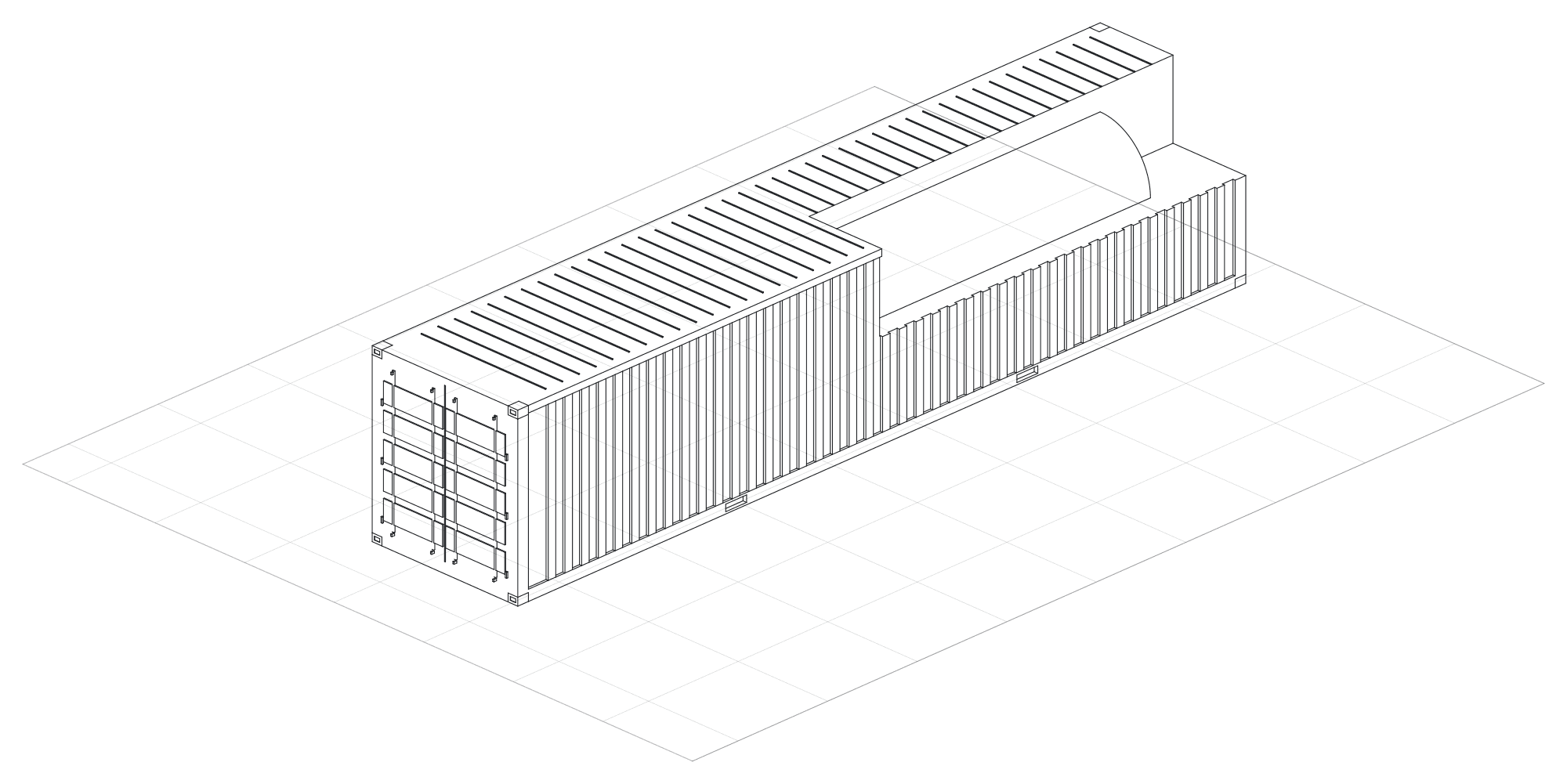
- Envelope
- 40 ft (12.19 m) ISO container · transportable by truck, rail, sea, or transport aircraft
- Control
- Pulse sequencing, interlocks, and AI control model running the reactor in real time
- Diagnostics
- Magnetic, optical, density, neutron, and proxy measurements feeding the control loop
- Deployment
- Behind-the-meter primary power · hyperscale datacenter, forward operations, microgrid / industrial, remote operations
- Team
- Six engineers · founder-led · San Francisco
- Status
- Concept-stage; non-nuclear bench evidence to be developed · engineering-diligence plan
III.Where Laurelin sits in the landscape
The architectural argument is sharpest when placed on the map of the wider field. Each public program is read against five coordinates — confinement geometry, fuel cycle, recovery posture, packaging envelope, operating mode. The Laurelin row is distinct on at least three coordinates from every other entry. The combination — compact pulsed FRC · 2H–2H· direct EM · container-class · pulsed — is a category that does not yet exist publicly, not a relocation of the rivalry inside an existing category. The table is a positioning, not a ranking.
| Program | Geometry | Fuel | Recovery | Packaging | Mode |
|---|---|---|---|---|---|
| ITER | tokamak | 2H–3H | thermal | utility-scale facility | quasi-steady |
| SPARC | HTS tokamak | 2H–3H | thermal | utility-scale facility | quasi-steady |
| W7-X | stellarator | 2H | thermal | large facility | quasi-steady |
| NIF | laser ICF | 2H–3H | thermal | national-lab facility | single-shot |
| TAE | beam-driven FRC | p–11B (long-term) | thermal / charged-product | facility-scale | quasi-steady |
| Helion | merging / compressing FRC | 2H–3He (bred) | direct EM | facility-scale | pulsed |
| Zap | sheared-flow Z-pinch | 2H–3H (long-term) | thermal | facility-scale | pulsed |
| General Fusion | magnetized target | 2H–3H | thermal | facility-scale | pulsed |
| Laurelin | compact pulsed FRC | 2H–2H (terminal) | direct EM (primary) | container-class | pulsed |
IV.Risk register
The architectural commitments bring a particular shape of risk surface. The risks below are named at the architectural level, as risks any program of this shape must confront. The mitigation categories are well-established in the public literature; the evidence artifacts on which closure depends are operating-record artifacts the program is built to produce.
V.Regulatory posture
A forty-foot transportable neutron-producing device is, under the post-ADVANCE Act framework, licensed by the Nuclear Regulatory Commission under 10 CFR Part 30 — the same regulatory surface as an industrial-irradiation facility — rather than as a utility power plant under Part 50 or Part 52. The fuel-cycle commitment to 2H–2H takes the program out of the Nuclear Suppliers Group trigger-list space that any 2H–3H program is, by construction, adjacent to. Deuterium itself moved from NRC licensing into ordinary Bureau of Industry and Security dual-use export control in October 2021.
The February 2026 NRC rulemaking on fusion-machine licensing clarifies the framework further. The Agreement-State licensing surface is the operational vehicle for siting and inspection on the cadence of an industrial-irradiation facility. The regulatory posture follows directly from the four architectural commitments; it is not a separate program decision.
VI.Program stage plan
The program runs as eight sequenced stages, S0 through S7, spanning Month 0 to Month 36. Each stage is closed by a specific operating-record artifact — a coil bench, a multi-coil pulsed sequence, a first-plasma article, a merge-and-compression article, a converter-coupled recovery measurement, a repetition-rate / life-test campaign, a construction-complete shielded reactor package — and each carries a corresponding financing logic: YC and pre-seed for S0 / S1, seed for S2 / S3, Series A for S4 / S5, larger hardware round and facility-scale capital for S6 / S7. First plasma is not a YC milestone; it is targeted by Month 14 on seed-funded execution, after the pulsed magnetic bench is safe, measured, and repeatable. A prototype with the full recovery chain measured at the protected boundary is available at the close of S5, Month 24. Construction-complete integrated reactor package is targeted by Month 36 and does not imply commercial net-electric operation by then. The cards below sit at the public level; the full component-by-component technical roadmap memo, with month windows, component build order, dependencies, and exit criteria, is available to qualified counterparties via the data room under mutual NDA.
IP and lab readiness
The opening stage is not a piece of hardware. It is the organisational and legal envelope inside which every subsequent piece of hardware is built: provisional IP protection, a counsel-cleared disclosure boundary that separates public material from patent-only material, the controlled data room, vendor and advisor network, the lab-space shortlist, and the safety plan that governs the first pulsed-power bench. Stage 0 closes when the company is legally and physically ready to start building coils, not when any coil exists yet. Months 0–1. 36-month horizon overall.
- Builds
- Provisional filing plan with patent counsel · counsel-cleared public / NDA / patent-only disclosure boundary · controlled data room and index · lab-space shortlist with vendor quotes · coil test plan and pulsed-bench safety plan · advisor and vendor network.
- Demonstrates
- Provisional filing plan · counsel-cleared disclosure boundary · lab shortlist · coil test plan.
- Unlocks
- YC / pre-seed start · authorisation to commit lab space, capacitor bank, and the first coil tooling · the disclosure boundary qualified counterparties receive on request.
YC / pre-seed coil bench
Stage 1 is the first execution proof. It delivers an operating lab bench and first measured coil data; it is explicitly non-nuclear and pre-plasma. The binding question is whether Laurelin can build representative coil articles in the 200 / 210 / 220 families and pull clean, repeatable electrical and magnetic traces off them on a safe pulsed bench. First plasma is not a YC milestone; what YC and pre-seed buy is the lab, the instrumentation, the coil data, and the IP hygiene to fundraise honestly. Months 1–2.
- Builds
- Operating lab and pulsed-power bench with grounding, barriers, capacitor-discharge procedures, interlocks, and fire/safety equipment · component 200 representative formation/transport coil article · component 210 compression coil article with retention and thermal sensing · component 220 inductive pickup/recovery article driven by a controlled magnetic pulse surrogate · first 275 / 276 buswork, protected loads, feedthrough and enclosure practices · targeted provisional IP filings.
- Demonstrates
- Operational lab · coil articles built · measured R, L, current, field, thermal, and induced-voltage traces.
- Unlocks
- YC / pre-seed proof of execution · authorisation to scope the integrated non-nuclear magnetic bench of S2 · the coil-data packet qualified counterparties receive on request under NDA.
Integrated non-nuclear magnetic bench
Stage 2 takes the individual coil articles of S1 and proves that Laurelin can run synchronised pulsed magnetic sequences across them. It is still not a plasma device. The coil articles become a small multi-coil bench with repeatable triggering, calibrated current probes, and the first version of the control stack (component 240): timing, interlocks, abort, shot logging, and automatic data capture. Measured magnetic fields are compared against simple coil models and finite-element or circuit models, and the 200 / 210 / 220 geometry and insulation choices iterate against measured heating, ringing, and voltage stress. Months 3–7.
- Builds
- Multi-coil bench upgrading the S1 200 / 210 / 220 articles · first build of component 240 control and waveform management — safe pulse sequencing, interlocks, abort, shot logging, automatic data capture · upgraded diagnostics (component 230) — coil-bench probes and DAQ · calibrated current probes and field maps · revised first-plasma bill of materials · updated invention disclosures with measured bench data.
- Demonstrates
- Repeatable pulsed magnetic sequences · calibrated field maps · safe abort / discharge · coil design revision.
- Unlocks
- Seed tranche 1 · authorisation to scope the first-plasma article (S3) · bench evidence that converts architecture into data-backed claim support for the seed-to-plasma narrative.
First plasma article
Stage 3 builds the first vacuum / plasma article using formation, fuelling, vacuum boundary, controls, and diagnostics. It is scoped to show formation and measurement, not fusion yield. The 110 / 120 formation and fuelling sections deliver controlled gas delivery, preionisation, and formation coils; the 200 coil set is upgraded from S1 / S2 learning; the 230 diagnostics package grows magnetic probes, current and voltage diagnostics, and imaging / spectroscopy where practical; the 240 control stack co-ordinates the pulse sequence safely and repeatably; and a simple 250 vacuum boundary with seals, pumping interfaces, and gas handling provides the plasma-compatible environment. First plasma is targeted by Month 14. Months 7–14.
- Builds
- Component 110 / 120 formation / fuelling sections with controlled gas delivery, preionisation path, and formation coils · upgraded component 200 formation coil set · component 230 magnetic probes, current / voltage diagnostics, imaging / spectroscopy where practical, and shot logging · component 240 timing, interlocks, DAQ, and accepted-shot logging · component 250 simple vacuum boundary, seals, pumping interfaces, and gas handling · cooling and feedthrough practices (270 / 276) adequate for low-duty tests.
- Demonstrates
- First plasma · reproducible timing · magnetic / plasma diagnostics · no fusion-performance claim.
- Unlocks
- Seed / seed-extension · engagement with strategic counterparties on the merge / compression article (S4) · conversion of the architecture into a data-backed first-plasma operating record by Month 14.
Merge and compression article
Stage 4 adds transport, central chamber, and compression. This is the point where component 150 (central merge-compression chamber) and component 210 (compression coil family) become integrated reactor hardware rather than stand-alone bench articles. Transport sections (130 / 140) are added once the first-plasma source is stable enough to translate or condition plasma states. Liner coupons (260) and cooling provisions (270) are added only to the level required for shot campaigns and inspection. The 230 diagnostics are used to classify merge timing, topology proxies, compression ratio, density and temperature proxies, and neutron / proxy signals if present. Months 11–20.
- Builds
- Component 130 / 140 guide / transport coil sections after basic formation is stable · component 150 prototype central merge-compression chamber spool with diagnostics access, compression-coil interfaces, replaceable liner provisions, and serviceable seals · upgraded component 210 chamber-integrated compression coil stack with thermal sensing and mechanical retention · component 260 liner coupons / cartridges and component 270 cooling provisions sized for shot campaigns and inspection · expanded 230 plasma diagnostics for merge timing and compression-response measurement.
- Demonstrates
- Merge timing window · compression-ratio proxy · density / temperature proxies · model-to-data comparison.
- Unlocks
- Series A technical basis if successful · authorisation to add the converter-coupled recovery sections of S5 · continuation / new provisional filings on merge / compression methods that arise from testing.
Converter-coupled pulse
Stage 5 tests direct conversion in plasma-coupled form. It follows, not precedes, classifiable merge / compression behaviour from S4. Modular component 160 / 170 direct-conversion regions are added downstream of the central chamber to give measured expansion and recovery timing. Component 220 recovery coil modules, derived from the S1 bench pickup article, become plasma-coupled. Protected buswork and DC-link or load-bank architecture (275), feedthrough and export enclosures with clamps, isolation, and fault handling (276), and converter timing and protection logic (240) close the recovery chain. The exit gate is measured recovered electrical energy above uncertainty at a protected takeoff, with safe handling of off-nominal pulses. Recovery fractions remain measured program results, not assumptions. Months 17–24. The close of S5 at Month 24 is the prototype-available milestone marked on Fig. 3.
- Builds
- Component 160 / 170 modular direct-conversion regions downstream of the central chamber · plasma-coupled component 220 recovery coil modules · component 275 protected buswork, DC-link or load-bank architecture · component 276 feedthrough / export enclosures with clamps, isolation, and fault handling · component 240 converter timing, protection logic, and accepted / aborted pulse handling · recovery-side diagnostics measuring time-integrated recovered energy and loss accounting.
- Demonstrates
- Measured recovered energy at protected electrical takeoff · off-nominal pulse handling.
- Unlocks
- Strategic / Series A proof point · authorisation to scope the repetition-rate and life-test programme of S6 · continuation filings on the recovery-coupling methods that arise from measurement.
Repetition-rate and life testing
Stage 6 is where a single-shot physics machine begins to become a reactor-engineering programme. Pulse count and duty factor are increased gradually while coil R / Ldrift, insulation health, feedthrough condition, and thermal equilibrium are monitored. Component 270 cooling is upgraded against measured heat loads in coils, chamber, feedthroughs, buswork, and liners. Component 260 liners are replaced and inspected on a defined interval; erosion, cracking, deposition, and service time are measured. Component acceptance criteria are established for the 200 / 210 / 220 coils, the 250 vacuum boundary, the 275 buswork, and the 276 feedthroughs. Months 21–30.
- Builds
- Upgraded component 270 cooling sized from measured pulse heating · serviceable component 260 liner cartridges and inspection cadence · qualified component 276 feedthroughs at higher repetition rate · upgraded component 240 controls for burst and steady operation · component acceptance specifications for 200 / 210 / 220 coils, 250 vacuum boundary, 275 buswork, and 276 feedthroughs.
- Demonstrates
- Burst / steady repetition-rate data · thermal equilibrium · insulation / vacuum / liner inspection.
- Unlocks
- Larger hardware round / non-dilutive financing · authorisation to commit shielding, activation controls, and the integrated reactor package of S7 · protected engineering details (serviceability, repetition-rate hardware, feedthrough qualification) that the IP workstream captures at this stage.
Shielded integrated reactor package
Stage 7 completes construction of the integrated reactor package and adds the facility-level controls needed for higher-yield 2H–2Hoperation. The target is construction completion by Month 36, followed by commissioning inside the regulated operating envelope. An as-built neutron / photon transport model is developed including penetrations and streaming paths; component 280 external shielding is added only after the source term and facility layout are specific enough to avoid false precision. Activation and shutdown-dose estimates are added for steel, copper, tungsten, liner material, shielding, and cooling loops; isotope accounting is added for 2H–2Hbranch products including tritium and helium-3. Operating limits are tied to measured radiation surveys and declared accessible-boundary dose objectives. Construction completion by Month 36 does not imply commercial net-electric operation by Month 36. Months 30–36.
- Builds
- Construction-complete shielded integrated reactor package · component 280 external shielding modules sized to measured source term and facility plan · as-built neutron / photon transport model including penetrations and streaming paths · activation / shutdown-dose estimates for steel, copper, tungsten, liner, shielding, and cooling loops · isotope accounting for tritium and helium-3 branch products · dose survey plan and facility deployment plan inside the regulated commissioning envelope.
- Demonstrates
- Integrated reactor construction complete · as-built neutronics model · dose survey plan · shielding / penetration closure · regulated commissioning envelope.
- Unlocks
- Facility-scale capital · construction complete by Month 36 · transition out of the bench and article campaign into a regulated commissioning programme on the Agreement-State licensing surface.